 The Drastic Test Pattern Generator can be used in conjunction with an install of HDRScope to provide a full featured audio video synchronization test. Test Pattern Generator sends a motion audio video sync pattern out and HDRScope receives the pattern along with its QR code and other details, and features an A/V Sync display that provides details on audio and video sync, and time in transit. Here is how to set up AV Sync testing.
The A/V Sync scope is added at the HDRScope level of DrasticScope. Test Pattern Generator can be purchased as a standalone software, or in conjunction with an HDRScope license for a complete A/V Sync testing solution.
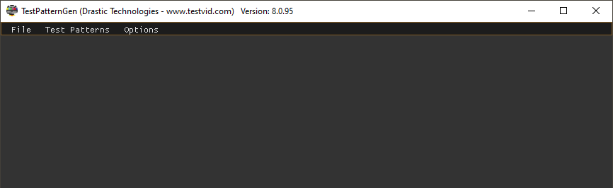
To set up AV Sync testing, first run Test Pattern Generator. It will need to be set up to output an A/V Sync pattern and its related options.
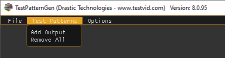
Click the Test Patterns pulldown menu, and click the Add Output option.
The new output opens with nothing in it. You will be prompted to right click on the window to open the Configure menu for the output. This is how you can add patterns and set up the output.
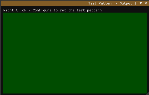
Right clicking on the empty test pattern produces the Configure option. Selecting Configure option opens the Config menu for the output.
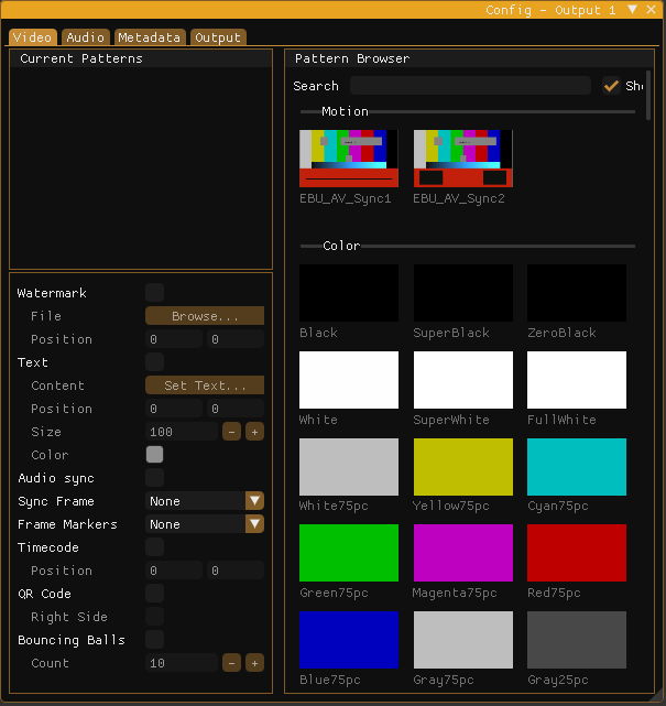
Patterns are added for each output by going to the Pattern Browser, and dragging it onto the Current Patterns section. Drag one of the available AV Sync patterns over and drop it onto the Current Patterns section to load it. Use the Sync Frame menu to set one of the sync frame conditions, i.e. either black frame or white frame.
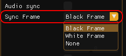
Click the QR Code checkbox to overlay it onto the output. The QR Code provides in-flight details about audio and video transit, which can be displayed in HDRScope.
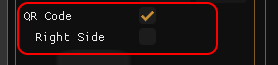
At this point the Test Pattern Generator will be sending out the AV Sync pattern, along with either a white or black flash, and the QR Code, for AV Sync detection.
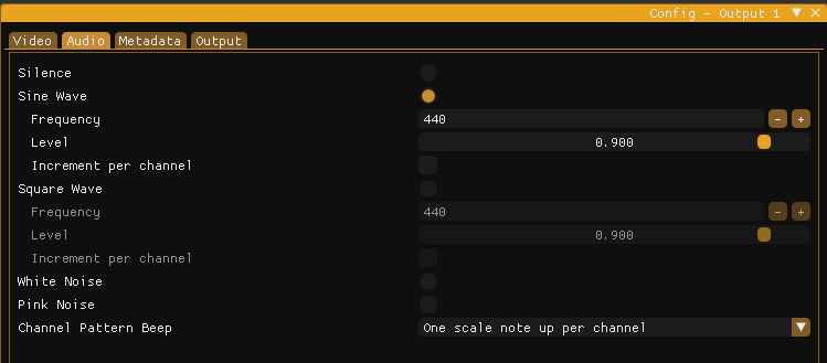
Confirm the audio parameters. The AV Sync pattern will use Silence, or a Sine Wave, or a Square Wave, to look for any offset.
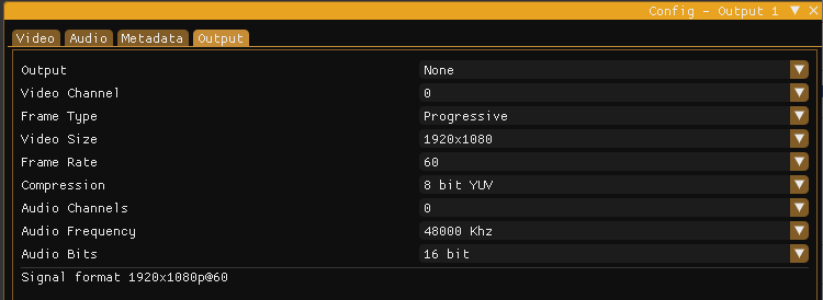
Set up the Test Pattern Generator to use the correct video standard and output device for your workflow.
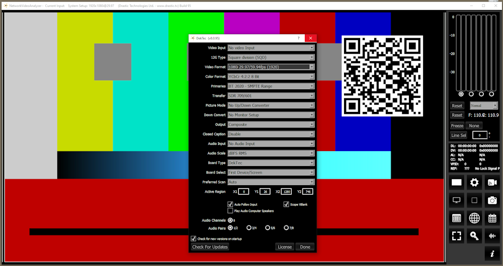
Next, run HDRScope and set its input to receive the signal from the Test Pattern Generator. In our example we are running Test Pattern Generator through a router, and receiving its output through a DekTec device.
Once you're seeing the output from Test Pattern Generator, you will want to add the A/V Sync display and set it up.
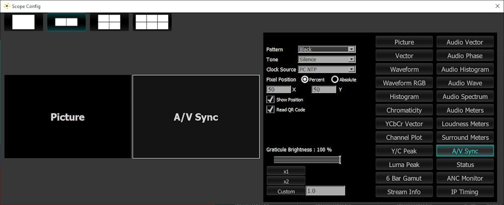
In Scopes Config, select the A/V Sync pattern. In the below image we have set up a 2 up display layout, with the Picture view on the left and the A/V Sync display on the right.
- Use the Pattern menu to set the condition, i.e. whether you are using Black, White, or another condition to trigger synchronization.
- Use the Clock Source pulldown menu to set HDRScope to the same clock source as the Test Pattern Generator.
- Click the Read QR Code checkbox to have this information displayed in the A/V Sync display.
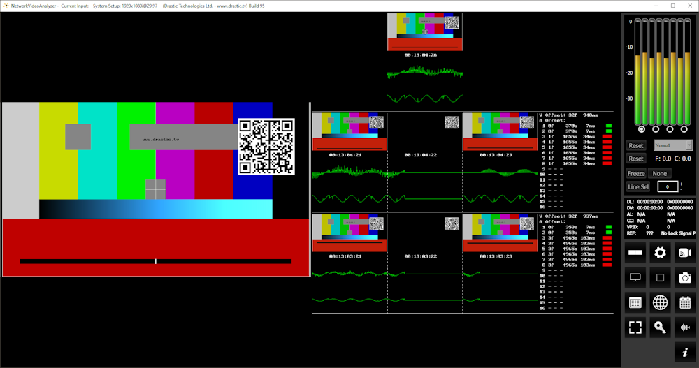
Now the signal can be seen in HDRScope. Below, the Picture View is on the left and the A/V Sync display is on the right.
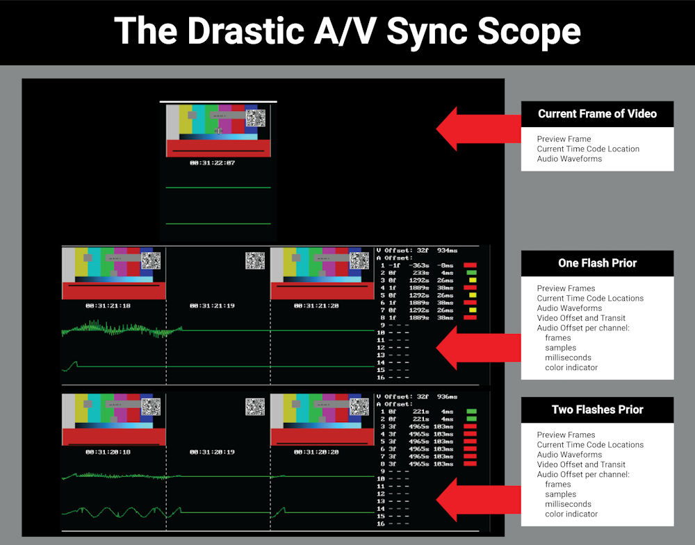
The A/V Sync display shows the current frame of video on the top, with video preview, time code, and audio waveforms. The second row displays details around the frame one flash prior, and the third row displays details about the frame two flashes prior. To the right of each are details about the video and audio elements, whether there is an offset, how many samples and milliseconds off if any, and a condition marker which can be either red (bad), yellow (not great, should be looked at), or green (is running fine with not too much offset).
2110Scope and HDRScope support the A/V Sync display and functions.